
| Turbo Header | |
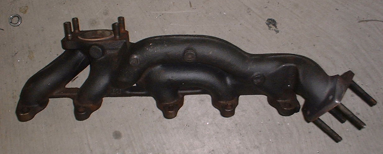
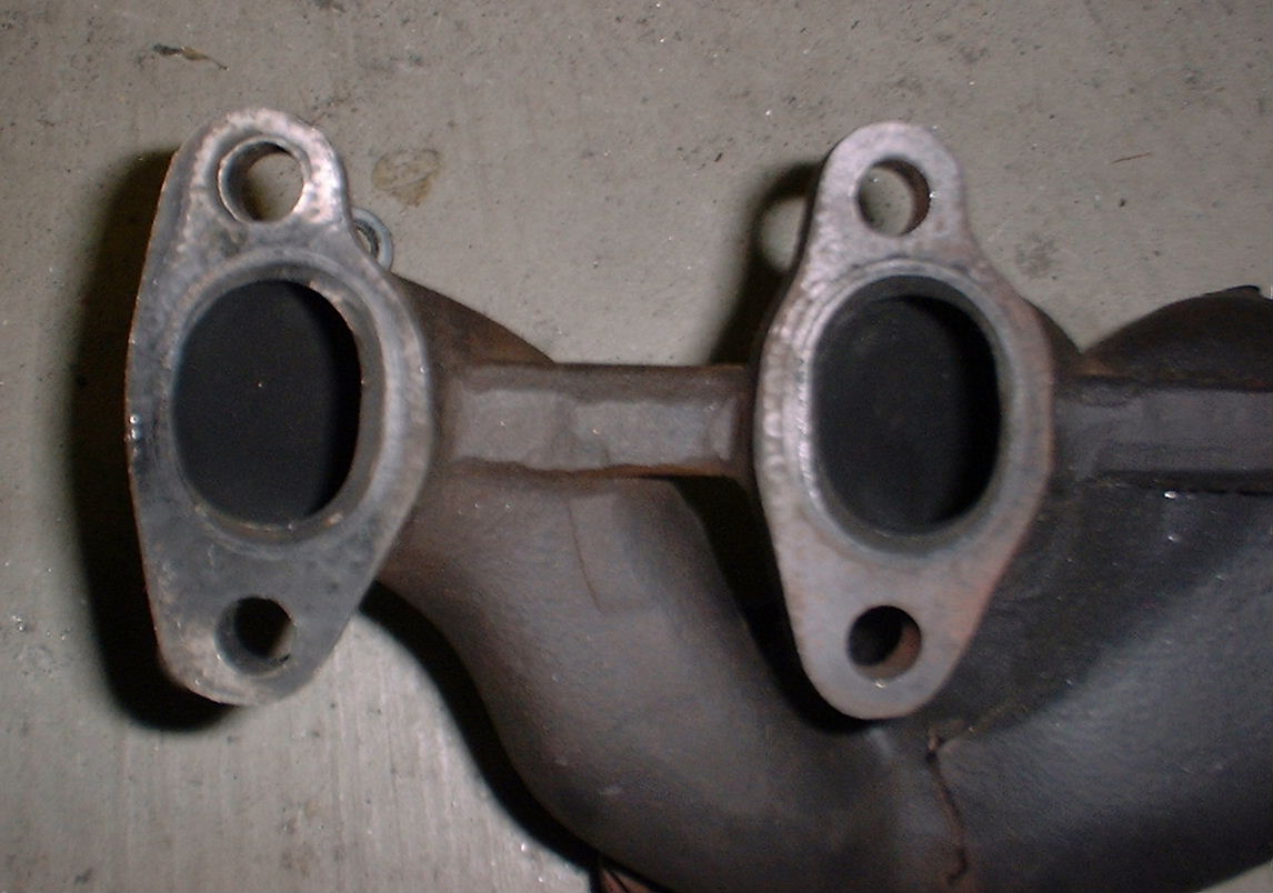
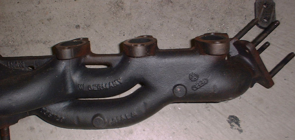
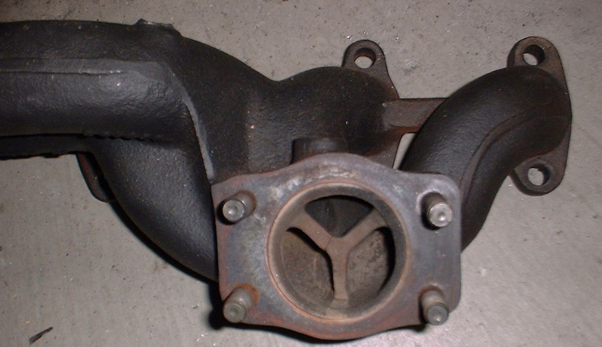
With the 20v motor there are lots of options for high performance manifolds from the factory, including the RS2 and even the SportQuattro manifold which is well proven past the 400hp mark. When comparing even the 3B manifold to the MC 10v manifold, the advantages are clear. The 10v exh. manifold is a severe victim to compromise and packaging concerns. Because the 10v motor is not cross flow, everything in the compartment is crammed into the passenger side of the engine, including the entire fuel system, induction system, alternator, AC, etc. Thus, the turbo and the manifold are forced to exist very close to the motor, inches from the frame rail. The result is exh. gas, traveling at high velocity from the exh. port, hitting the solid wall of the exh. manifold(runners 1, 2 and 3-5)and making a 90 degree+ turn to change directions not only once but two or three more similar transitions before it makes to the opening of the turbo. The variance in length of the runners varies from 4" to over 11" between cylinder #1 and #5. Also, the wastegate is vented very poorly in the stock manifold, venting only runners 3, 4, and 5 in the process. Also, the collector, while engineered to maximize velocity of the pulses at low RPM, manages to become very restrictive at higher RPM and boost levels where maximum flow is most critical. Plus, if all this is not bad enough, the suckers crack, leak, warp and pull studs on a regular basis. Frankly, more thought was likely taken in creating access for the hard to reach nuts than performance. My estimate is that the factory manifold, while more than enough for stock application, is a limiting factor in making power over 250hp.
A Few Options
I mention these, but none hardly worth justifying the effort, or especially the expense:
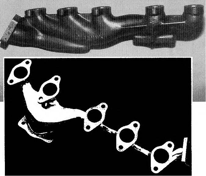
• Two Piece Manifold- the exh. manifold from the factory 200 Quattro cars was updated to a two-piece design, with an expanding accordion to prevent cracking. It is said to also flow "10% better", but I have yet to see proof of that. Cost is about $800-1000 (gulp) from the factory, and is a direct fit when using the MC downpipe. Use this piece if you are looking for cracking resistance, but I don't consider it much of a performance upgrade. An extrude honed one-piece will likely flow much better than this.
• Dialynx- did a replacement for the factory one-piece manifold..its basically an archaic log-design that is said to warp like a "wet-noodle" and pull studs merrily along the way. New price is about $1k...no thanks...
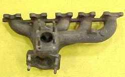
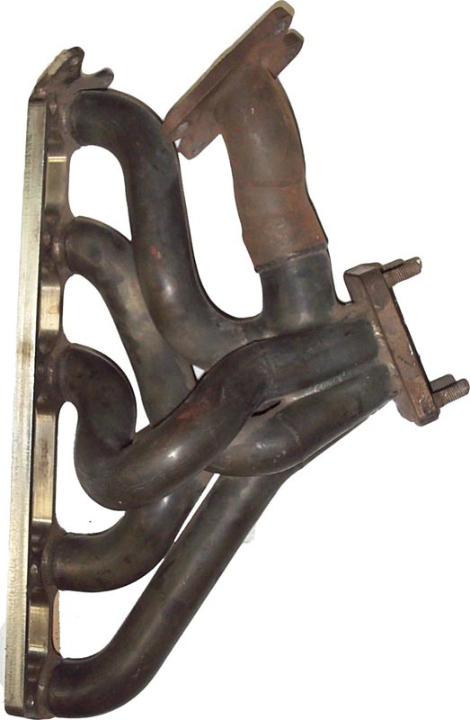
• TransAm Header pic- Will not fit a Type 84 or 89 chassis, puts the turbo right into the frame rail, in fact, the header cannot even be put flush against head the clearance is so poor. Not sure about the clearance in a Type 44, but I suspect it won't fit there either. Considering the cost and availability of any of these pieces, its best not considered an option anyway.
Clean Sheet Design
If you want to get the job done, you sometimes have to do it yourself. After extensive research on the net and in whatever written information I could find, I began building up a design, taking into consideration different factors:
• Runner Length- it has been proven that longer, straighter runners increase flow over short, convoluted runners. By placing the turbo in the fender where the CIS box used to be, runner length can be set at about 10-15", with very few bends, none more drastic that a simple 90 degree at most.
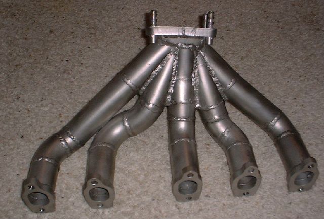
• Runner size- a consideration must be made between maximum flow and low speed velocity. The material I used for runners was available in 1.1" or 1.4" diameters. Since 1.1" would be a bit smaller than stock, and I am looking for high maximum output, I chose 1.4" as a reasonable, yet aggressive ID for the runners. Just looking at this header, you will see that it is built for flow.
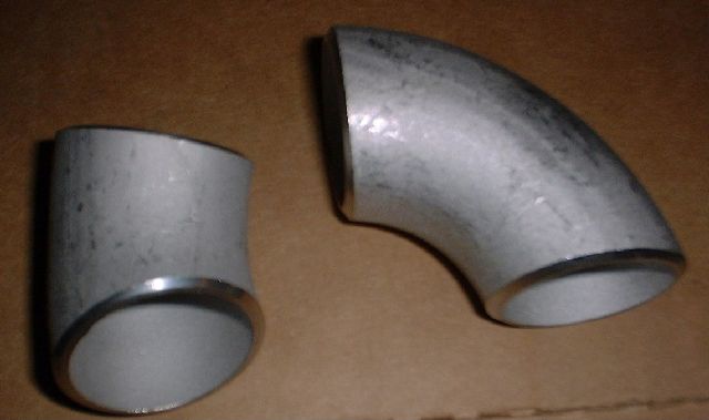
•Manifold Material- in the high temp. environment of the turbo manifold, the utmost temperature resistance is required. Because of this, standard mild steel is completely unacceptable. Even standard 16g 304 stainless will eventually fail in an unacceptable amount of time under heavy turbo use. In the thinner gauge material such as 16 or 18 gauge, 321 is really the only alloy suitable. But, with increased material thickness temp. resistance also increased (as in the stock cast iron manifolds). To reduce cost but still create a strong, durable manifold I used schedule 10 butt-weld 304 stainless hydraulic pipe (also known as WeldEls). These are a pain to work with as they are hard and thick, but they lay up nicely, create smooth bends, weld strongly and create a very nice manifold when it's all done.
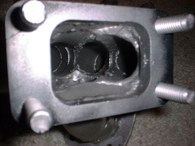
•Collector Design- the collector is a critical component of the header, it functions to bring together the outputs of all the different ports and merge them into the inlet of the exhaust turbine. All runners should merge together smoothly as possible. Also, the collector contains the output to the wastegate, and a smooth transition centrally located to all runners enables smooth, accurate boost control of the wastegate. Also, the volume of the collector is very important. By dumping all the runners into a large volume collector or box as some do, the velocity of the exh. pulse will be dissipated when it travels out of the relatively small runner into a large collector that is many time the volume. Thus, attention must be paid to the transitioning diameter of each runner into the collector, and ensure that a good balance between flow and velocity are considered.
•Head flanges- I chose not to use one big flange at the head, but separate flanges for each runner. For one, this was much easier to design, as a CAD drawing was created from one exh. gasket, and 5 identical parts were created from one design. Since there is no off the shelf gasket that properly lays out the relation of all 5 ports and all 10 studs to each other, this was a more difficult design. Also, individual flanges allow more flexibility of the manifold for expansion cycles. I had flanges cut out of 3/8" cold rolled 304 stainless. The turbo inlet flange is 1/2" stainless, with welded 1/2" 316 stainless studs.
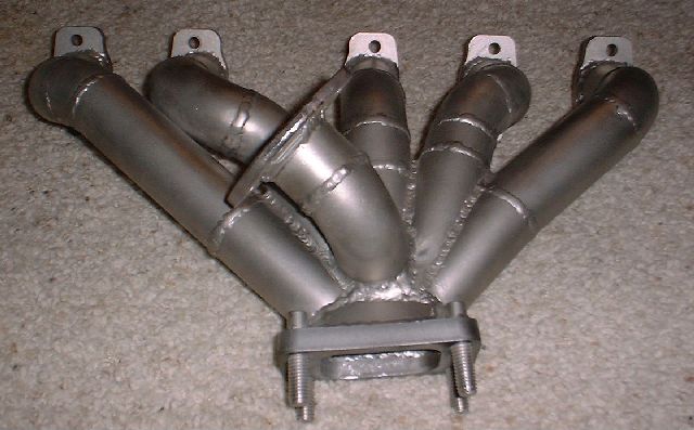
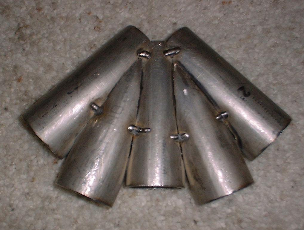
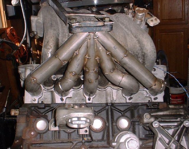
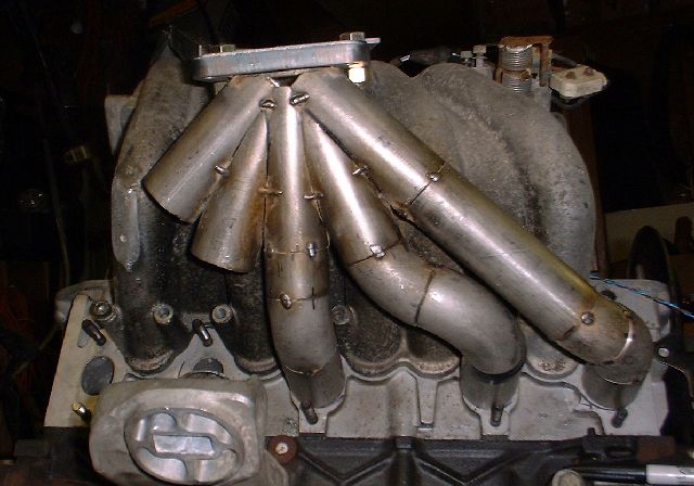
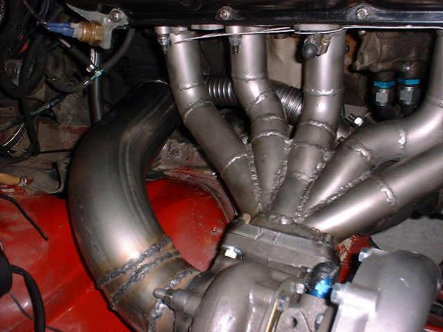
•Construction- By far the most important consideration in the construction of the header was placement of the turbo and the clearance of the runners in relation to the intake manifold and other peripheral components in the engine compartment. Because of this, I built the header on a jig consisting of an actual block, head, intake manifold, and bracket to hold the final placement of the turbo. Then, each runner was carefully fitted, taking also into consideration clearance access to intake manifold and head studs for the header itself. To ensure proper clearance in the actual in-car fit, the whole assembly was taken off the jig and fitted in the car repeatedly. Once everything was MIG tack-welded in place, a TIG was used to meticulously weld over all seams and joints to ensure a strong, airtight weld. Here you can see the header fully tack welded ready to be TIG'd, and another part way under construction
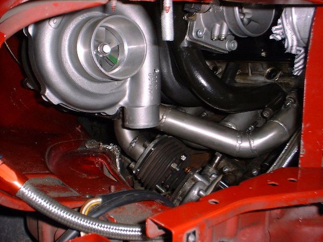
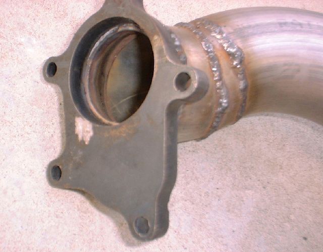
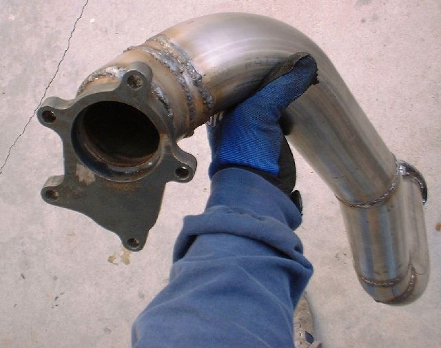
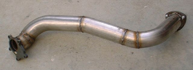
•Down Pipe- a 3" diameter was chosen for more than enough flow coming out of the turbo. I used 304 stainless mandrel bends from Burns Stainless. Also, to transition from the 2.25" turbine outlet to the 3" pipe, I used a 2"-3" hydraulic transition. See different shots here: 1 2 3 4
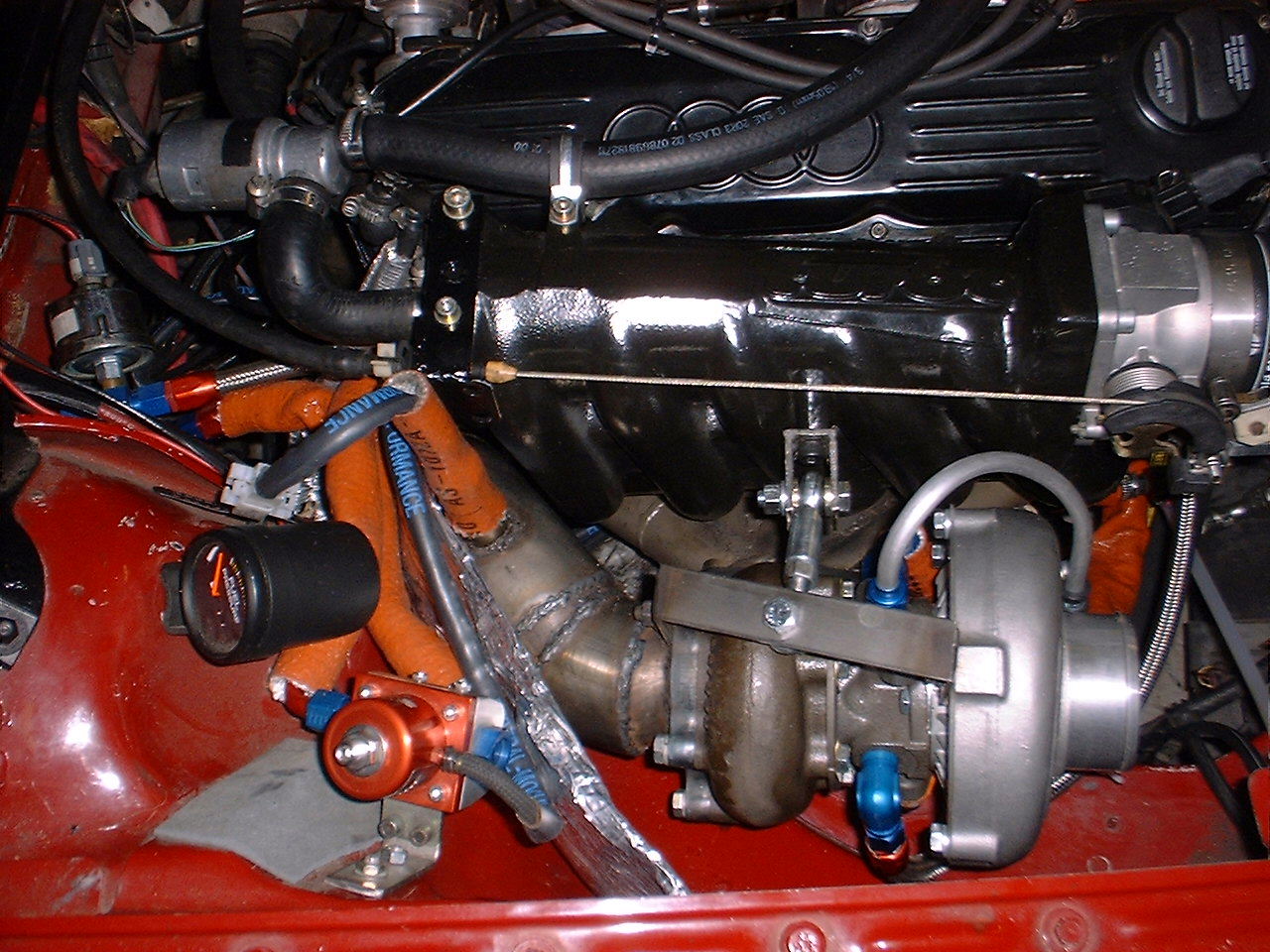
| Some shots of the completed installation | |
 |
 |